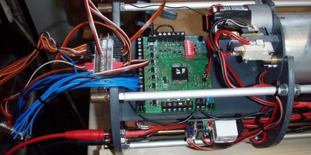
Und ich sach noch: “Der Speicher reicht nicht!”
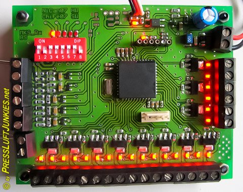
Nr 3 aus der ersten Serie von 7 Stück
Und zwar immer genau in dem Moment in dem ich mit dem anpassen fertig war. Sorry Christian, aber das muss jetzt raus. Ja, und dann war es soweit. Der Speicher des Mikroprozessors reichte wirklich nicht mehr, vor allem deswegen weil wir immer wieder neue Ideen hatten die auch gespeichert werden wollten.
Nils und Christian waren aber so vorausschauend einen Prozessor zu nehmen den es in verschiedenen Ausführungen gibt. Die Pinbelegung war bei allen gleich so dass nur noch die Firmware neu kompiliert werden musste. Wir nahmen nicht den nächst größeren sondern den übernächst größeren, jetzt hatten wir 4-mal soviel Speicher. Tja, cool dachte sich Christian, jetzt kann ich ja die Doppelbelegungen wieder entfernen. Gedacht (natürlich nicht abgesprochen) und getan! Und was ist mit mir? Ich hatte mal wieder die Hosen unten und musste erneut mein Konzept überarbeiten. Diesmal war es aber wirklich das letzte Mal.

MKS verbaut in Projekt 1710 „Makrele“
Es blieb mir nichts anderes übrig als alle Einstellungen in einer Datenbank zu verwalten denn es sind mittlerweile über 650 Einstellpunkte! Ist aber so eine Datenbank inkl. Suchroutinen erst mal programmiert, wird alles sehr einfach und übersichtlich. Desweiteren habe ich eine mks Klasse programmiert die alles Einstellungen quasi als Objekt darstellt. Neuerungen und/oder Änderungen können jetzt sehr schnell implementiert werden. Irgendwann war der Zeitpunkt gekommen in dem wir alle auf einem Nenner waren und alles wurde im Vorfeld abgesprochen.
Als die erste Version funktionierte wurde uns erst einmal das ganze Potential bewusst. Es ist ein großer Unterschied ob man Einstellungen per HEX-Editor im Speicher macht oder einfach per Pull-Down-Box einstellt. Das testen der Funktionen ging ab diesem Zeitpunkt schnell von der Hand. In der Testphase am Anfang war auch abzusehen dass es sehr gut wäre ein paar Situationen aufzuzeichnen. Z.B. einen Failsafezähler der einem nach der Fahrt Rückschlüsse über die Funkverbindung gibt. Auch ein Zähler, der jedesmal erhöht wird wenn die Bordspannung unter den unteren Schwellwert rutscht, wurde eingebaut.
Übersicht im Vordergrund

MKS Sendemodule in einer Graupner Fernsteuerung
Wenn man 6 Eingänge und 22 Ausgänge hat wird einem recht schnell klar dass wahrscheinlich die Übersicht leidet. Dies wollte ich vermeiden, deswegen habe ich editier bare Bezeichnungen eingebaut die auch auf den Buttons zu lesen sind. Ich wollte nicht dass man immer in einer Liste nachschauen muss auf welchem Ausgang (Button) das Schnorchelkopfventil liegt. Und dies ist nicht nur bei den Ausgängen sondern auch noch bei den Eingängen und Funktionen.
Diagnose muss sein!

Diagnose über ein angeschlossener Laptop
Ich habe beim Testen schnell gemerkt dass es nicht immer möglich ist auf die bunten Lichter des mks zu schauen. Wenn das Boot zu ist geht das nicht. Deswegen hab ich eine Diagnose eingebaut die den Status der Ein- und Ausgänge anzeigt. Dazu muss allerdings noch ein Kabel aus dem Boot führen, bei einem Pressluftboot Mentzscher Bauart ist das leicht möglich. Gleichzeitig werden auch die Spannungen an den Eingängen angezeigt, sowie Failsafe- und Unterspannungszähler.
Allerdings war es immer noch schwierig die Hysterese der Eingänge zu testen, dies lag daran dass die aufgeschriebenen Schwellwerte recht geschrieben aussehen. Ich wollte was grafisches, sowas hatte ich noch nicht gemacht. Ich entschloss mich eine Art Monitor zu programmieren, ähnlich wie bei einem Oszilloskop. Auf diesem Monitor sollten man Schwellwerte und die aktuelle Spannung ablesen können. Es war gar nicht mal so schwer die Routinen dazu zu schreiben. Und ich glaube das Ergebnis kann ich sehen lassen. Das Testen der Eingänge, Schwellwerte und Hysterese war hiermit sehr viel einfacher. Auch wurden noch kleinere Fehler entdeckt und so manches doch noch mal umgeworfen weil es mehr Sinn machte.
Die Daten
Natürlich lässt sich jede Konfiguration abspeichern und laden. Man kann zwar auch die Daten aus dem mks auslesen, die Anschlussbeschreibungen werden allerdings nicht übermittelt. Dafür ist im Mikroprozessor beim besten Willen kein Platz. Beim einspielen der Konfiguration in dem mks werden die Daten sofort wieder ausgelesen und byteweise verglichen. Danach werden nochmals die berechnete Checksumme des mks und die des Programms verglichen. Erst wenn alle Vergleiche erfolgreich sind bekommt man eine positive Meldung angezeigt. Den Datenvergleich kann man jederzeit auch einzeln durchführen.
Funktionsumfang
- 5 analoge Eingänge mit denen man Spannungen von 0-35V messen kann
- 1 analoger Eingang, gekoppelt mit der Versorgungsspannung
- 16 direkt schaltbare Ausgänge
- 5 Ausgänge die programmgesteuert schaltbar sind
- 1 Flip-Flop Ausgang
- Alle Ausgänge können mit 1 Ampere belegt werden
-
-

Diagnose mit übersichtlicher Hysterese
Dies ist die kleine Geschichte hinter der Entwicklung eines anpassbaren Mehrkanalschalters für U-Boote mit Presslufttechnik. Wir kombinierten unsere Fähigkeiten und schafften eine wunderbare Elektronik. Nils Canditt war für das Hardware-Layout verantwortlich. Christian Feldmann programmierte die Firmware für den Mikroprozessor und ich schrieb die PC Software mit der man den MKS programmieren kann. Sascha Amberger testete den MKS auf Herz und Nieren in seinem U-Boot mit dem Risiko es wegen eines Softwarefehlers zu verlieren. Aber alles lief reibungslos und funktionierte von Anfang an unglaublich Zuverlässig. Dieses Projekt brauchte gerade mal eine Wintersaison um sieben Prototypen nebst Software funktionsfähig zu bauen.
Nachdem sich der MKS in vielen Booten bewährt hat wurde es Zeit dieser Hardware einen Namen zu verpassen. MKS war eigentlich nur interne Name. Wir entschlossen uns den Namen an die Software anzupassen:
- Zentrale Software
- Zentrale RX
- Zentrale Mini RX
- Zentrale TX
-
-
And I said, “The memory isn’t enough!”

Number 3 from the first series of 7 pieces.
And always at the exact moment when I finished adjusting. Sorry, Christian, but this has to come out now. Yes, and then it happened. The memory of the microprocessor really wasn’t enough anymore, mainly because we kept coming up with new ideas that also needed to be saved.
But Nils and Christian were so foresighted to choose a processor that comes in different versions. The pin layout was the same for all, so only the firmware needed to be recompiled. We didn’t choose the next bigger one, but the next-to-next bigger one, now we had four times as much memory. Well, Christian thought, cool, now I can remove the double assignments. Thought (of course not discussed) and done! And what about me? Once again, I was caught off guard and had to revise my concept again. But this time it was really the last time.
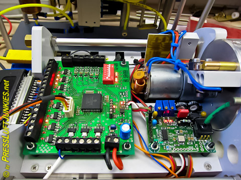
MKS installed in Project 1710 “Makrele” (mackerel).
I had no choice but to manage all settings in a database because there are now over 650 adjustment points! But once a database including search routines is programmed, everything becomes very simple and clear. Furthermore, I programmed an MKS class that represents all settings as objects. Innovations and/or changes can now be implemented very quickly. Eventually, the time came when we were all on the same page and everything was discussed in advance.
When the first version worked, we first realized the full potential. There is a big difference between making settings via a HEX editor in memory or simply setting them via pull-down box. Testing the functions became quick and easy from this point on. In the testing phase at the beginning, it was also foreseeable that it would be very useful to record a few situations. For example, a failsafe counter that gives you conclusions about the radio connection after the trip. Also, a counter that increases every time the onboard voltage drops below the lower threshold was installed.
Overview in the foreground.
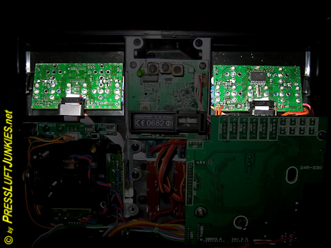
MKS transmitter modules in a Graupner MC-24
When you have 6 inputs and 22 outputs, you quickly realize that the overview is likely to suffer. I wanted to avoid this, so I included editable labels that can also be read on the buttons. I didn’t want people to always have to look in a list to find out on which output (button) the snorkel head valve is located. And this applies not only to the outputs but also to the inputs and functions.
Diagnosis is a must!
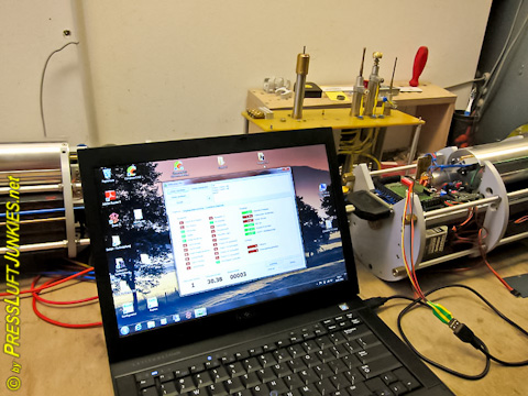
Diagnosis via a connected laptop.
During testing, I quickly realized that it’s not always possible to rely on the colored lights of the MKS. When the boat is closed, this is not feasible. Therefore, I implemented a diagnosis function that displays the status of the inputs and outputs. However, this requires a cable to lead out of the boat, which is easily achievable with a Mentzscher-type compressed air boat. At the same time, the voltages at the inputs are also displayed, along with fail-safe and under-voltage counters.
However, it was still difficult to test the hysteresis of the inputs because the written threshold values looked quite abstract. I wanted something graphical, something I hadn’t done before. I decided to program a kind of monitor, similar to an oscilloscope. On this monitor, one should be able to read threshold values and the current voltage. Writing the routines for this was not as difficult as I thought. And I believe the result speaks for itself. Testing the inputs, threshold values, and hysteresis became much easier with this tool. Additionally, some minor errors were discovered, and certain aspects were reconsidered because they made more sense.
The data
Of course, every configuration can be saved and loaded. While it’s possible to read the data from the MKS, the connection descriptions are not transmitted. There simply isn’t enough space in the microprocessor for that. When loading the configuration into the MKS, the data is immediately read out again and compared byte by byte. Then, the calculated checksum of the MKS and that of the program are compared again. Only when all comparisons are successful will you receive a positive message. The data comparison can also be performed individually at any time.
Features
- 5 analog inputs for measuring voltages from 0-35V
- 1 analog input coupled with the supply voltage
- 16 directly switchable outputs
- 5 outputs programmatically switchable
- 1 flip-flop output
- All outputs can handle up to 1 ampere
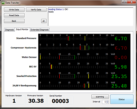
Diagnosis with clear hysteresis
This is the little story behind the development of an adaptable multi-channel switch for submarines using compressed air technology. We combined our skills and created a wonderful electronics system. Nils Canditt was responsible for the hardware layout. Christian Feldmann programmed the firmware for the microprocessor, and I wrote the PC software for programming the MKS. Sascha Amberger tested the MKS extensively in his submarine, risking its loss due to a software error. But everything went smoothly and worked incredibly reliably right from the start. This project only took one winter season to build seven functional prototypes along with the software.
After the MKS proved its worth in many boats, it was time to give this hardware a name. MKS was originally just an internal name. We decided to align the name with the software:
- Central Software
- Central RX
- Central Mini RX
- Central TX


