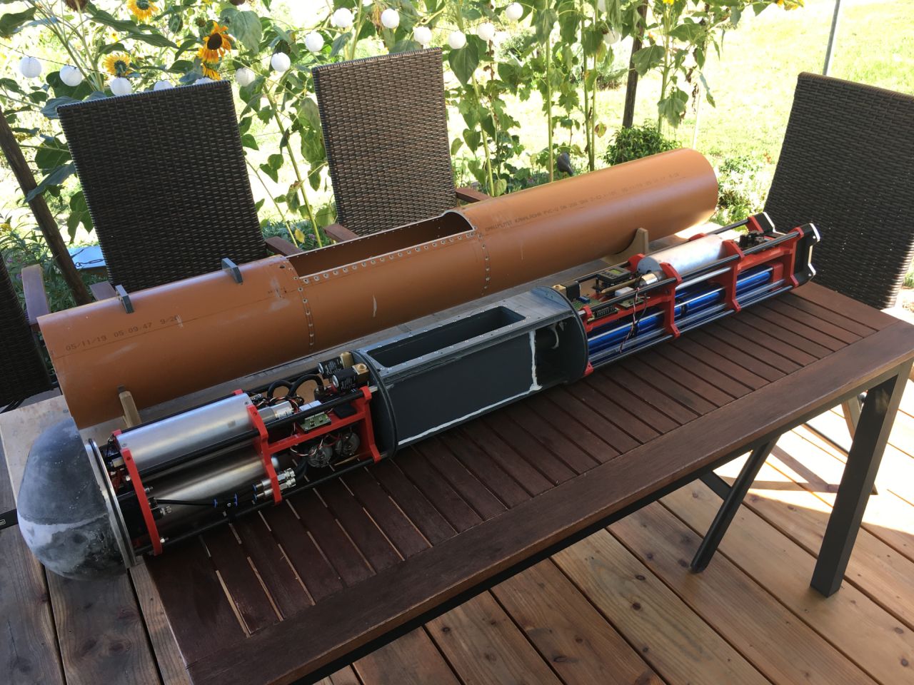
Dekadenz und Design oder so…
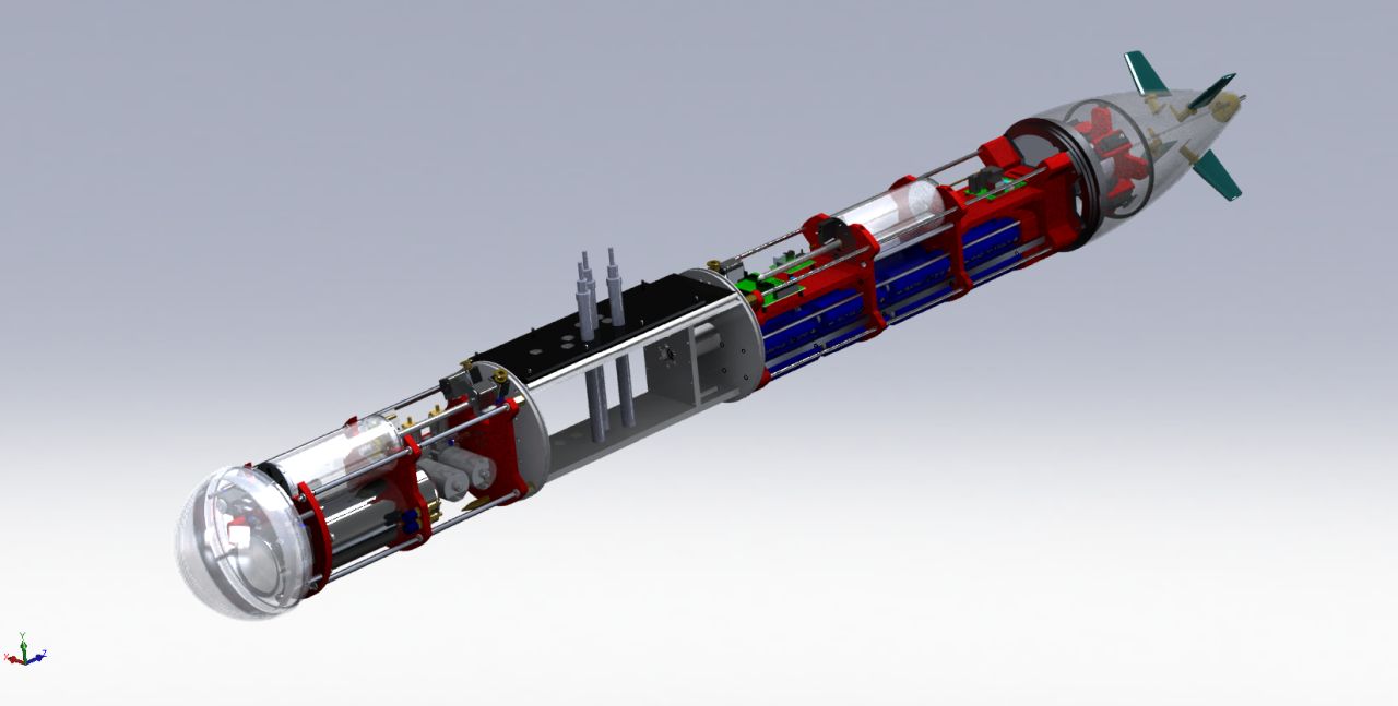
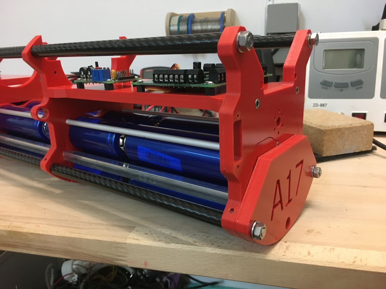
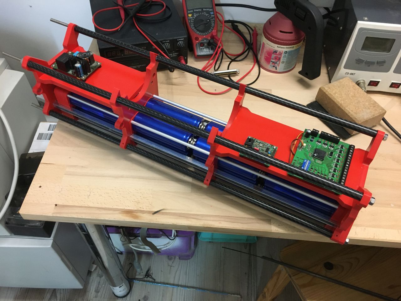
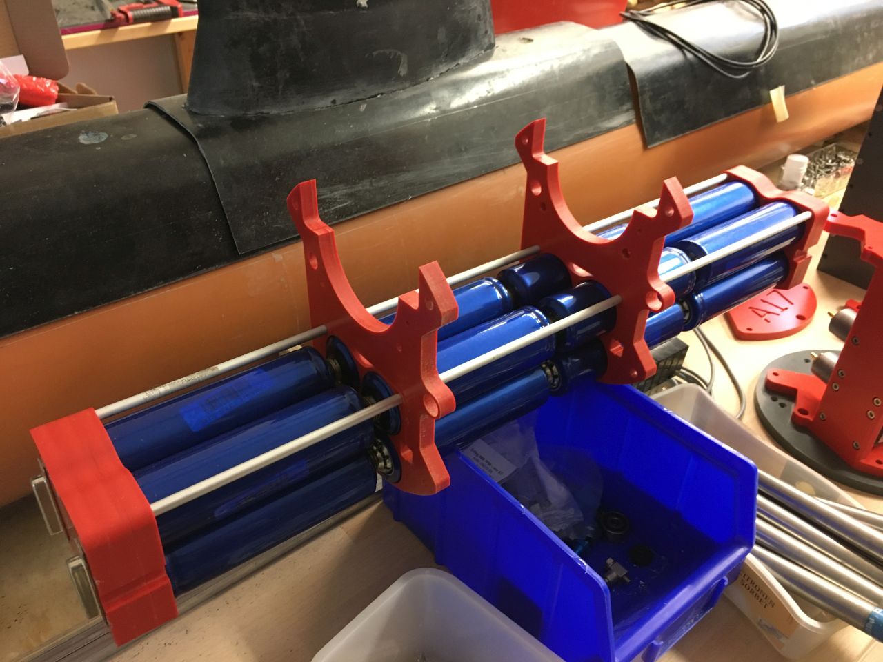
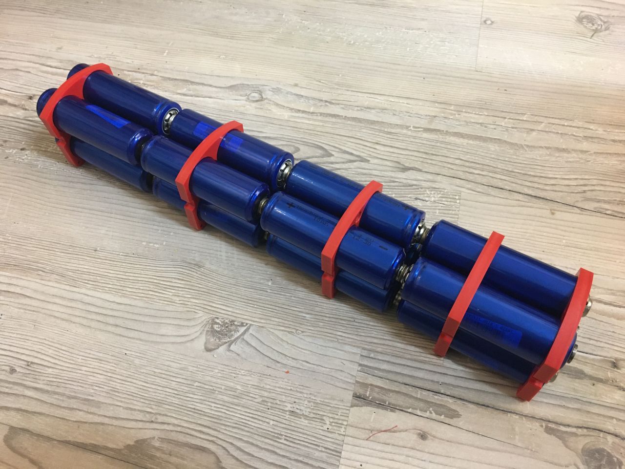
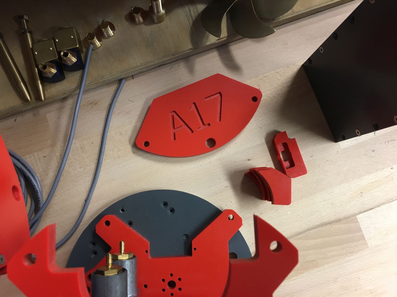
Das Boot wurde komplett im CAD (Solidworks) geplant. Ich wollte diesmal auch ein wenig was fürs Auge bauen, es sollte alles sehr aufgeräumt sein und auch im inneren etwas „spacig“ wirken. Also anstatt graues, diesmal rotes PVC und die Spanten etwas abgespeckt und optisch aufgehübscht. Als Energiequelle kommen 16 LiFePo-Zellen 10Ah zum Einsatz, was eine Bordspannung von etwa 26V bei 20Ah ergibt. Der Platz ist da, also Akkus rein anstatt Blei. Das Ganze auch wieder als Modul auf Aluschienen gelagert. Der Akku kann so komplett herausgezogen werden und hat außen keine Kabel. Die Abstandhalter sind sehr dekadent in Kohlerohr mit Abstandhaltern aus GFK entstanden, im Inneren die bewährte M6 Gewindestange. Alles ist in Module unterteilt, was der Wartungsfreundlichkeit entgegen kommt. Damit der Verschlussring später auch mit der Welle und den Ruderachsen fluchtet, wurde eine Lehre angefertigt, die auf der Antriebswelle verschraubt werden kann. Diese trägt auch gleichzeitig die Löcher der Ruderachsen, somit fluchtet alles zwangsläufig und kann in einer Runde eingeklebt werden. Für solche Verklebungen nutze ich Endfest 300 und tempere die Verklebungen bei ca. 60°C. Im Turm geht es ohnehin recht eng zu, erschwerend kommt hinzu, das die A17 gleich 2 doppelwirkende Ausfahrgeräte hintereinander hat. Die 2. Stufe sollte ebenfalls pneumatisch ausfahren, also war hier einiges an Zeichenarbeit im Vorfeld zu erledigen.
Decadence and Design or something like that…
The boat was completely planned in CAD (Solidworks). This time, I wanted to build something visually appealing; everything should be very tidy and have a somewhat „spacey“ feel on the inside. So, instead of gray, I opted for red PVC this time, and the frames were slimmed down and visually enhanced. As a power source, 16 LiFePo cells, each with a capacity of 10Ah, are used, resulting in an onboard voltage of approximately 26V at 20Ah. There’s enough space, so I went for batteries instead of lead. Everything is mounted on aluminum rails as modules again. The battery can be completely removed and has no external cables. The spacers are quite luxurious, made of stainless steel pipe with fiberglass spacers, while inside, the reliable M6 threaded rod is used. Everything is divided into modules for ease of maintenance. To ensure that the closure ring aligns with the shaft and the rudder axles later on, a jig was made that can be bolted onto the drive shaft. This jig also accommodates the holes for the rudder axles, ensuring alignment, and can be glued in one go. For such bonding, I use Endfest 300 and temper the joints at around 60°C. The tower is already quite tight, and it’s made more challenging by the fact that the A17 has two double-acting extension devices in a row. The second stage should also extend pneumatically, so a lot of drafting work had to be done beforehand.
Das Querstromruder
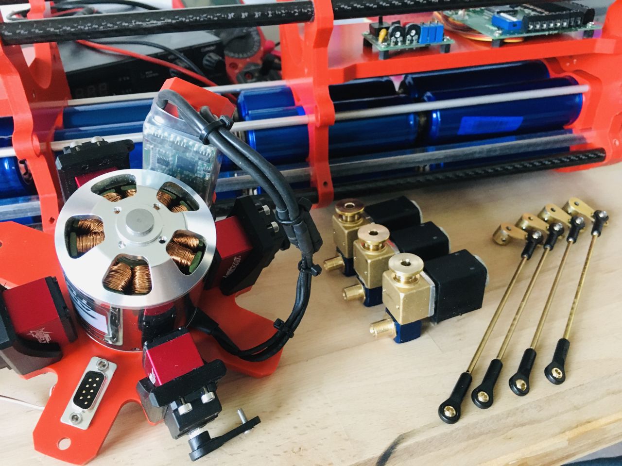
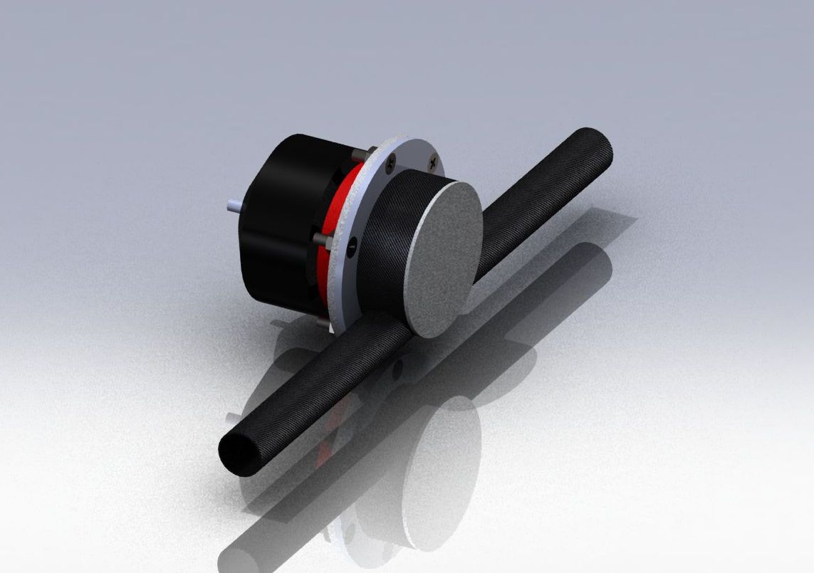
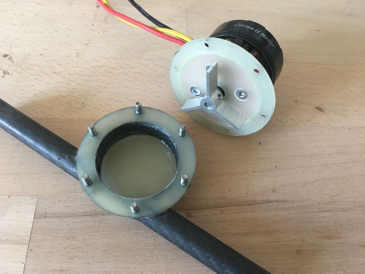
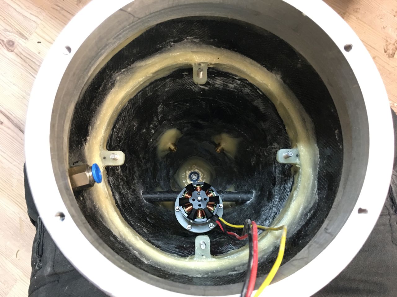
Durch die Länge des Bootes war der Einbau eines Querstromruders obligatorisch. Die letzten Boote hatten jeweils 2 oder 4 Campingpumpen von „Reich“ im Einsatz. Diese fördern etwa 18l/min und drehen ein schweres Pressluftboot ausreichend schnell. Da diese in den letzten Jahren horrend teuer geworden sind und sehr Platzfressend im ohnehin engen Heckteil, musste eine Alternative her. Bestenfalls mit Brushless, klein aufbauend und leistungsstark. Nach langer Suche blieb nur der Eigenbau, was den Vorteil hatte, den Motor direkt ans Bordspannungsnetz anpassen zu können. Nach dem Aufbau des Prototyps wurde dieser ausgiebig getestet. Der Wasserdurchsatz liegt bei etwa 22l/min und einer Stromaufnahme von unter 2A im Vollastbetrieb. Der Pumpenkörper besteht aus einem Abfallstück CFK Rohr, die Platten und Ringe sind 2mm GFK, das Strahlrohr ist ebenfalls aus CFK. Der Rotor hier noch zum Testen aus Alu, wurde dann final aus Messing hergestellt. Abgedichtet ist alles mit einem Lippring und im Pumpenkörper mit einem O-Ring.
The Transverse Thruster
Due to the length of the boat, the installation of a transverse thruster was mandatory. The previous boats each used 2 or 4 camping pumps from „Reich“ in operation. These pumps deliver about 18l/min and spin a heavy pneumatic boat sufficiently fast. However, in recent years, they have become exorbitantly expensive and very space-consuming, especially in the already tight rear section. An alternative was needed, preferably with brushless technology, compact, and powerful. After a long search, only self-construction remained, which had the advantage of being able to directly adapt the motor to the onboard power supply. After the prototype was built, it was extensively tested. The water flow rate is approximately 22l/min with a current consumption of under 2A at full load. The pump body is made from a scrap piece of carbon fiber composite (CFK) pipe, the plates and rings are 2mm fiberglass (GFK), and the jet pipe is also made of CFK. The rotor, initially made of aluminum for testing purposes, was then finally made from brass. Everything is sealed with a lip ring and an O-ring inside the pump body.
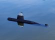
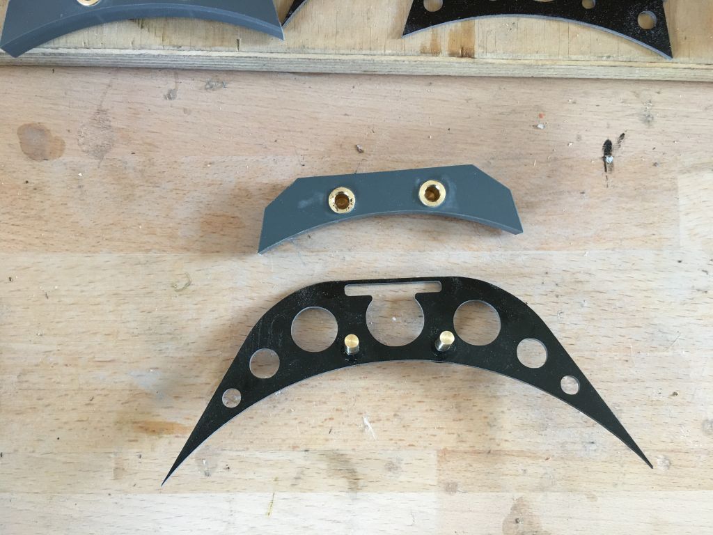
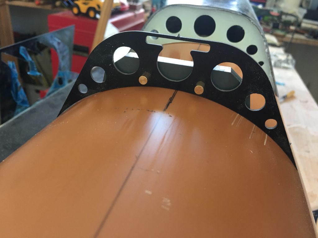
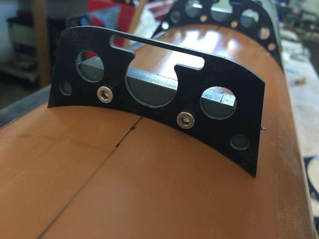
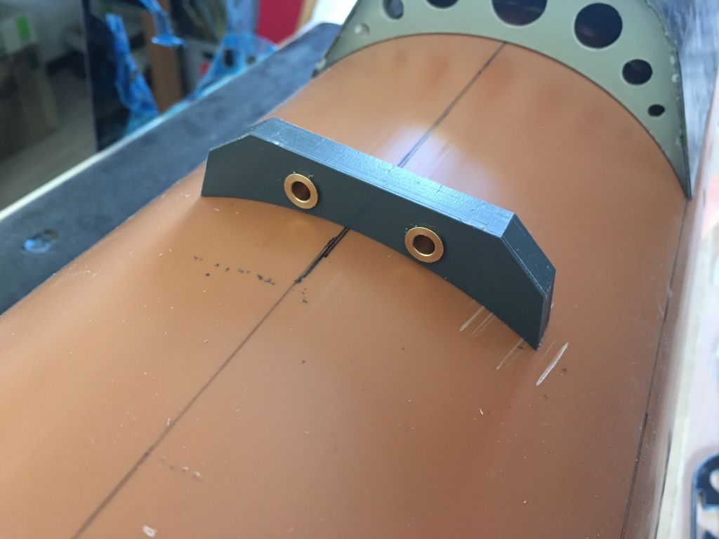
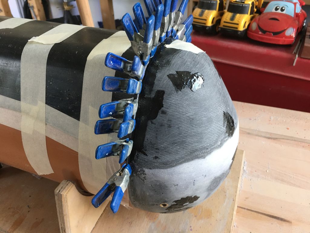
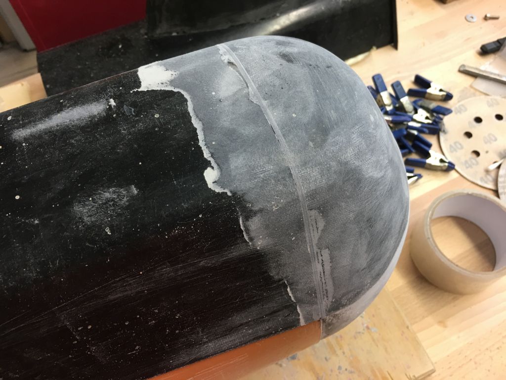
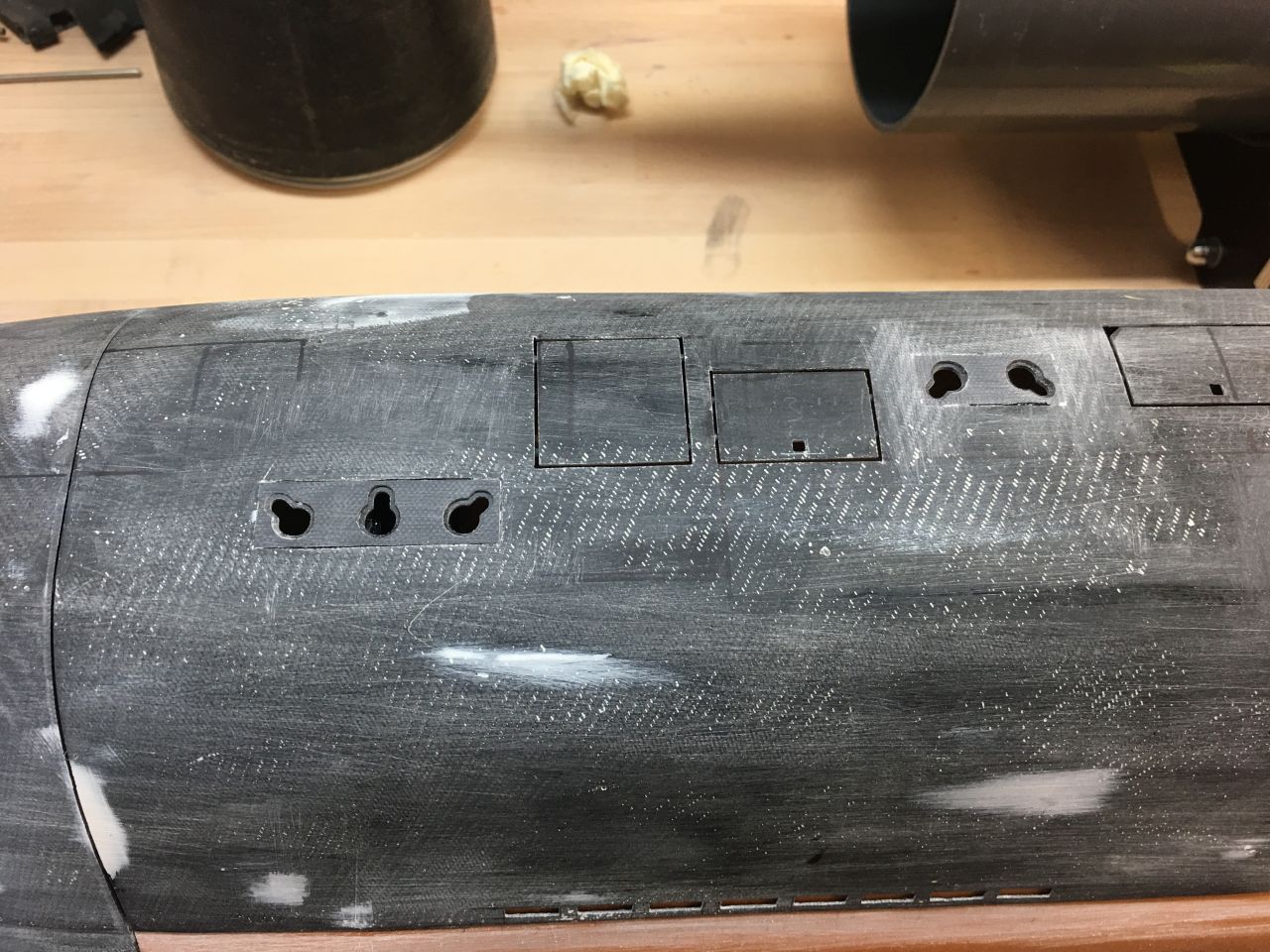
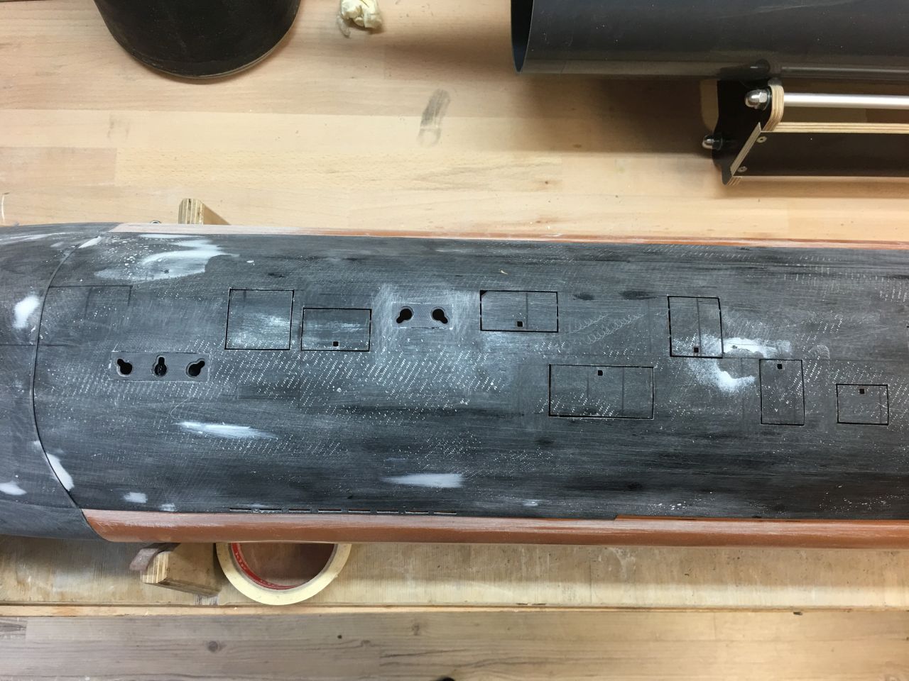
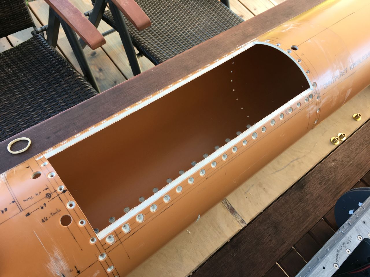
Das Deck
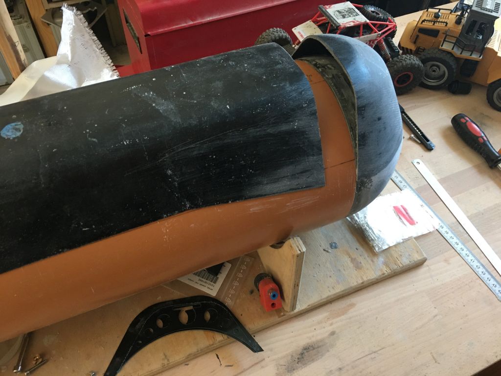
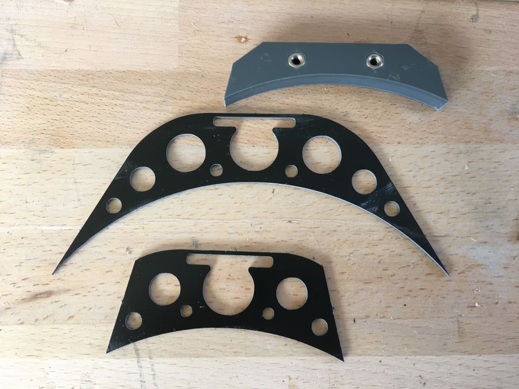
An meinen letzten beiden Booten war das Deck als ein einziges Teil ausgeführt und konnte komplett abgenommen werden. Es verbleibt nur ein kleines Bug- und Heckstück auf dem jeweiligen Ende. Das A-17 Deck sollte etwas anders aufgebaut werden. Das Mittelteil wird dreiteilig, so kann später einfach der Turm abgenommen werden. Vorteil hierbei ist, das es kein sehr langes Deck gibt, das nicht ganz sauber aufliegt und eine unschöne Deckskante erzeugt. Ein Nebeneffekt ist, das ein kleines Teilstück besser zu handhaben ist. Nachteil sind natürlich weitere Trennstellen im Decksverlauf. Damit dieser Nachteil keiner ist, muß genau gearbeitet werden, um keine Spalte entstehen zu lassen. Zwecks Wartung sollten die „festen“ Deckteile dennoch abnehmbar sein. Daher habe ich unterhalb des Decks mehrere Spante aus 1mm GFK eingeplant. Davon fixiert einer das Deck, der Zweite dient als Verschraubung. Ein paar Bilder beschreiben besser das Vorgehen und die Ausführung der Teile.
The Deck
On my last two boats, the deck was constructed as a single piece and could be completely removed. Only a small bow and stern piece remained at each end. The A-17 deck was intended to be built slightly differently. The middle section will be divided into three parts, making it easy to remove the tower later on. The advantage here is that there won’t be a very long deck that doesn’t sit perfectly flat, creating an unsightly deck edge. Additionally, handling a smaller section is easier. The downside, of course, is having additional separation points along the deck’s course. To mitigate this downside, precise work is necessary to avoid creating gaps. For maintenance purposes, the „fixed“ deck parts should still be removable. Therefore, I’ve planned several 1mm fiberglass (GFK) frames beneath the deck. One of them secures the deck, while the second serves as a screw fastening point. A few pictures would better illustrate the process and execution of these parts.
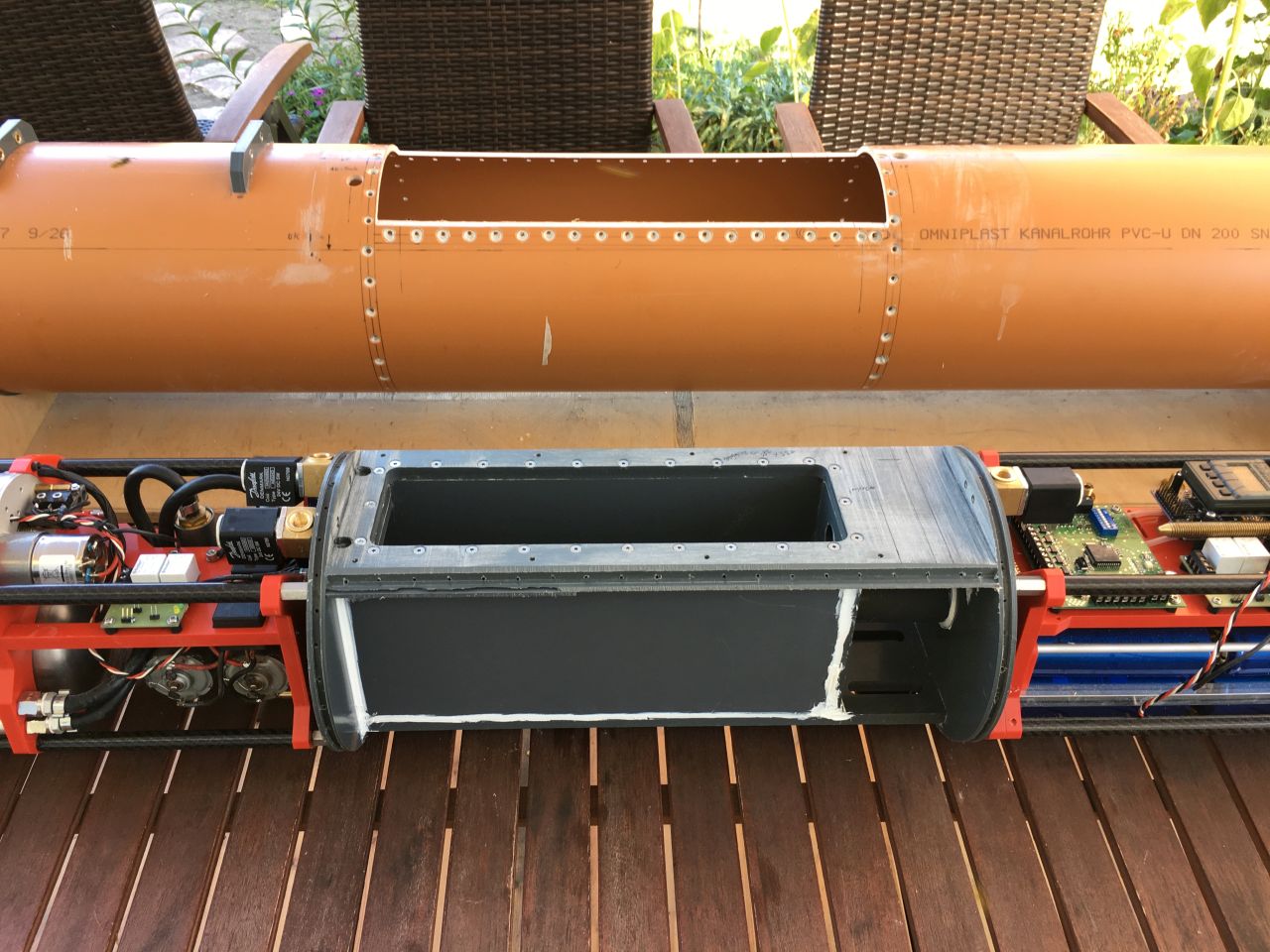
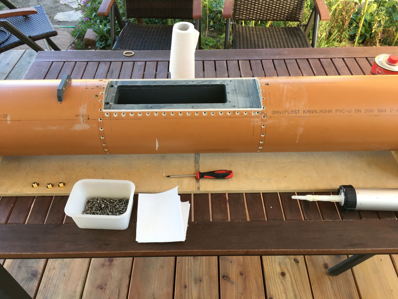
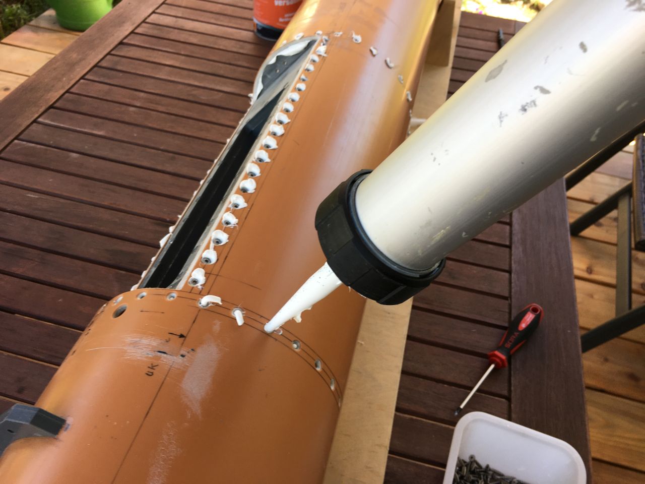
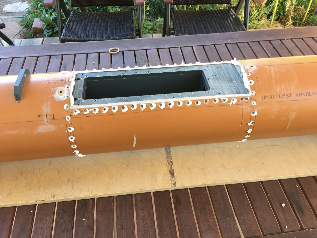
Der Haupttank
Am Haupttank kann nichts wesentliches verändert oder verbessert werden. Die Stromdurchführungen verlaufen anders als bei meinen älteren Booten im Trockenbereich, der Rest bleibt so, wie damals von Lothar Menz entwickelt. Eingeklebt wird der Tank inzwischen mit Dekasyl, Sikaflex hatte in der Vergangenheit des Öfteren Ärger bereitet. Der Tank selbst hat umlaufen eine Nut, in der sich die Masse verteilt. Gehalten wir alles von VA-Schrauben die rundum eingedreht werden. Die Masse selbst wird durch die Schraublöcher eingespritzt, bis sie zum nächsten Loch austritt, also alles wie immer…
The Main Tank
There can be no significant changes or improvements made to the main tank. The cable penetrations run differently from my older boats, in the dry area, but the rest remains as developed by Lothar Menz back then. Nowadays, the tank is bonded using Dekasyl instead of Sikaflex, which has caused trouble in the past. The tank itself has a groove running around it where the compound is distributed. Everything is held in place by stainless steel screws that are screwed all around. The compound is injected through the screw holes until it emerges from the next hole, so everything is as usual…
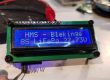
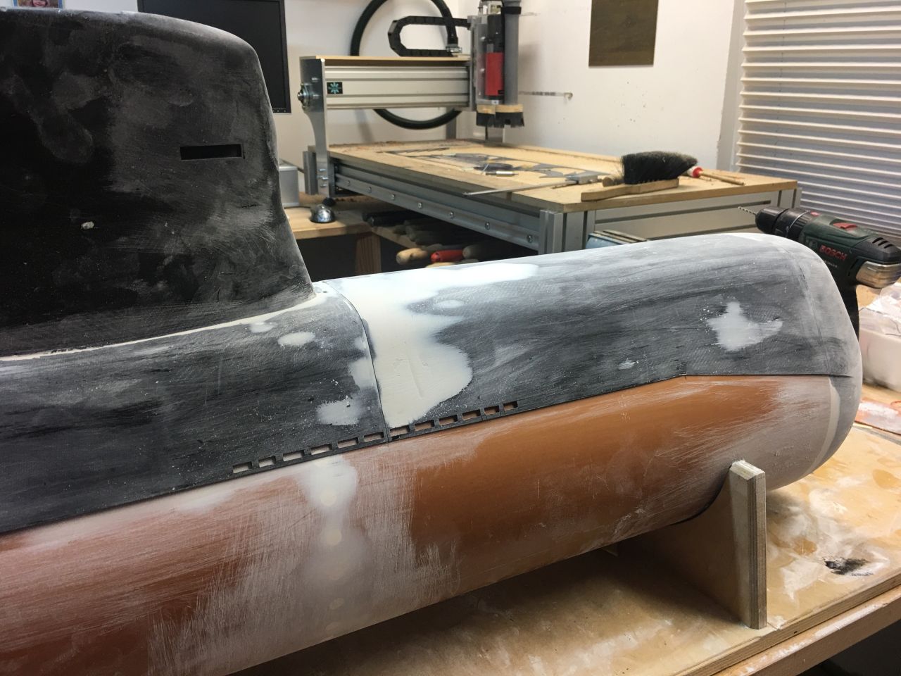
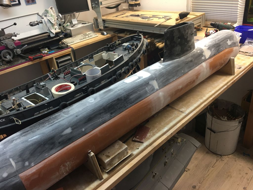
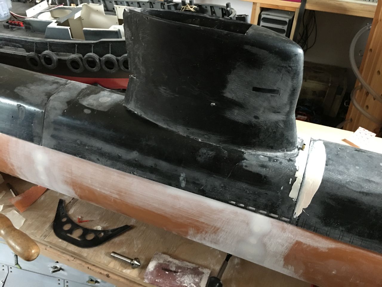
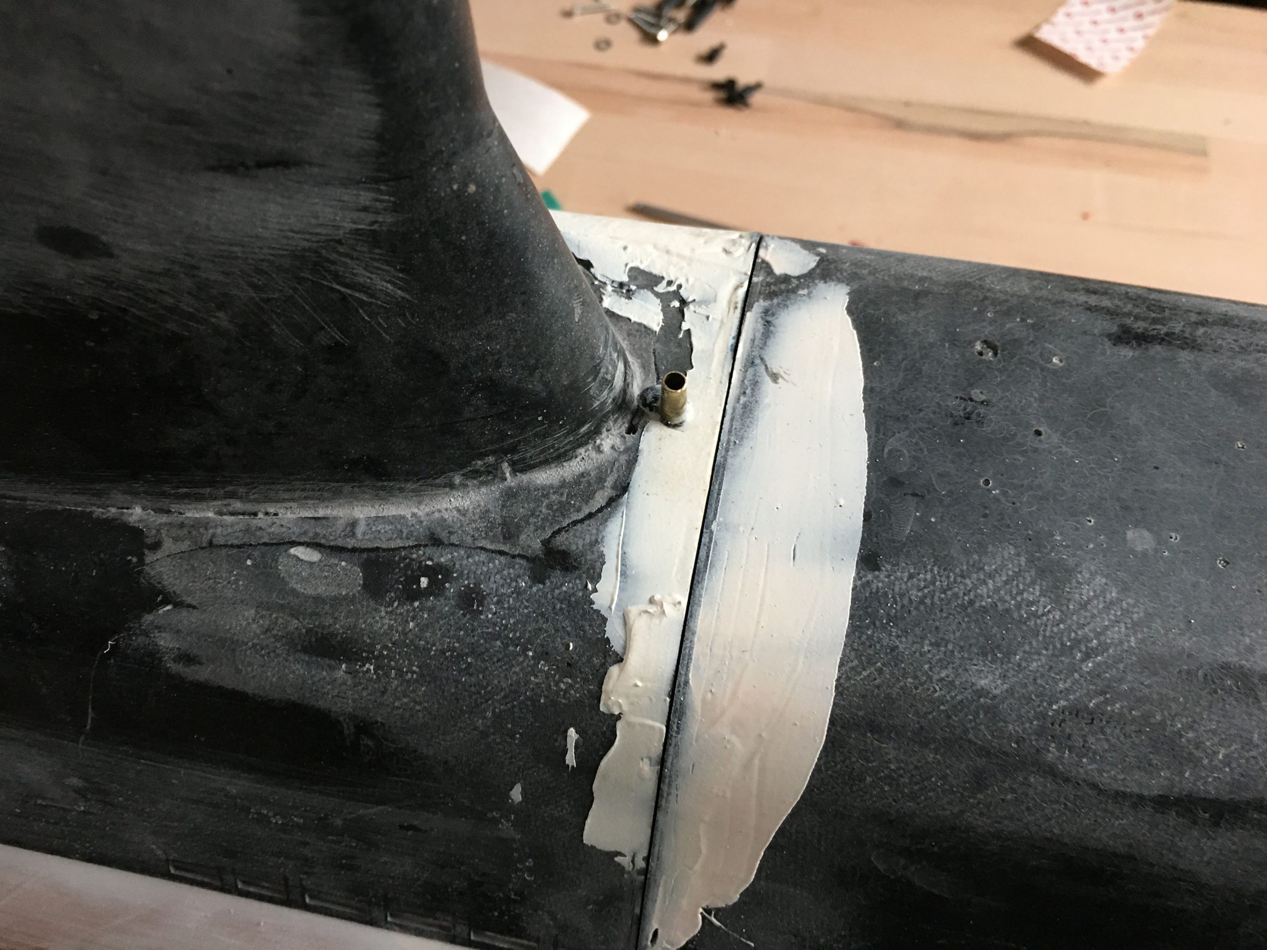
Magnete und andere Unsichtbarkeiten
Der Verschluß des Turms mußte nun auch gebaut werden, um das restliche Deck zu verkleben. Ich wollte das möglichst unsichtbar haben, also kam im hinteren Teil ein Passtück mit Magneten zum Einsatz und vorne ein Schraubverschluß. Das Drehteil vorne beherbergt eine gegen herausfallen gesichert die Schraube. So kann der Turm einfach aufgesetzt werden und wird dann mit nur einer Schraube gesichert. Die Magnete halten alles in Position. Im nächsten Schritt wurden auch gleich die verbliebenen Löcher der Tankschrauben verspachtelt. Damit die Oberfläche glatt wird sind mehrere Schleifgänge nötig was einiges an Zeit frisst. Ob alles sauber verschliffen ist zeigt spätestens die Grundierung….
Magnets and Other Invisibilities
The closure of the tower had to be built now to bond the remaining deck. I wanted it to be as invisible as possible, so a fitting piece with magnets was used in the rear part, and a screw closure in the front. The rotating part in the front securely holds the screw in place to prevent it from falling out. This allows the tower to be easily placed and then secured with just one screw, while the magnets hold everything in position. In the next step, the remaining holes of the tank screws were also filled with putty. Achieving a smooth surface requires several sanding passes, which takes quite some time. Whether everything is cleanly sanded down will be evident at the latest after priming…
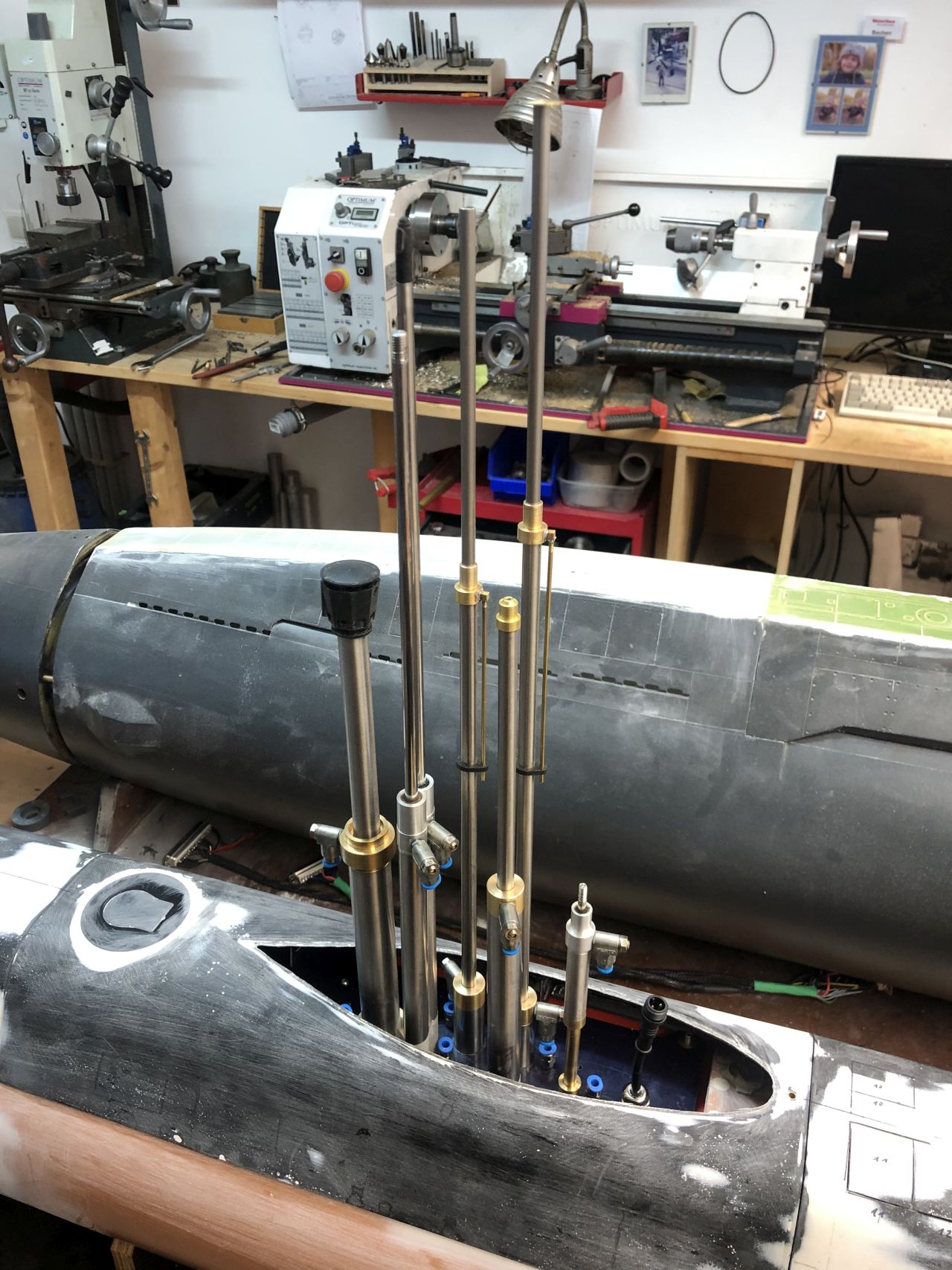
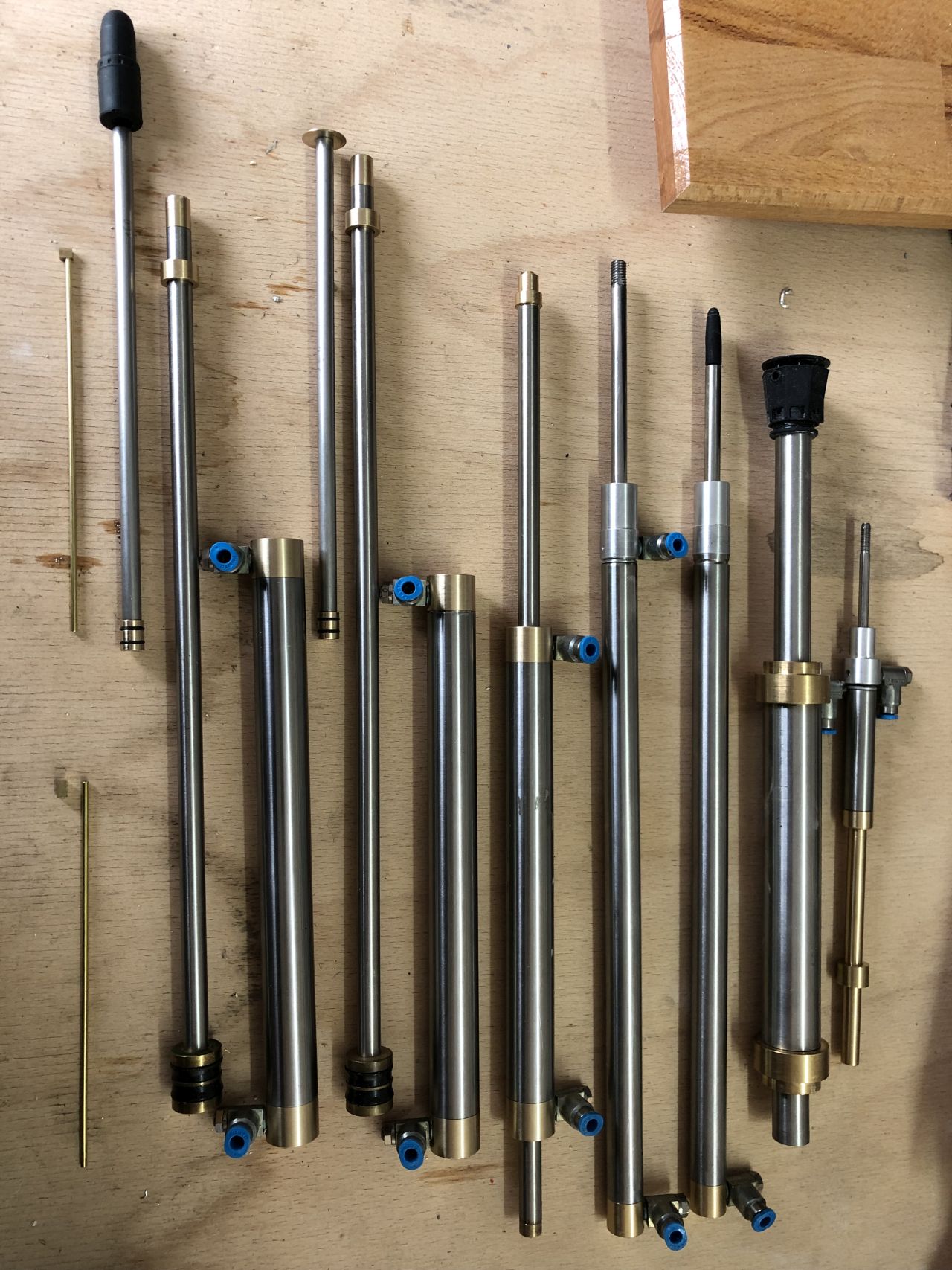
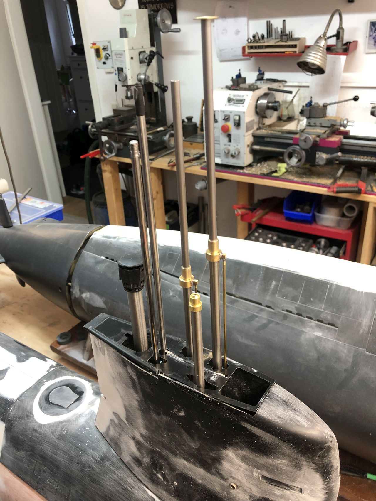
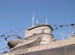
Massenweise Drehteile und Kolben
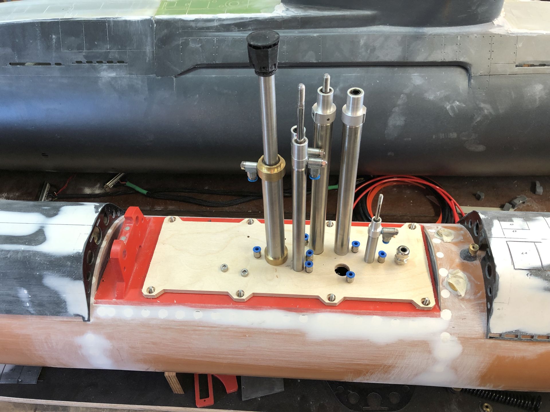
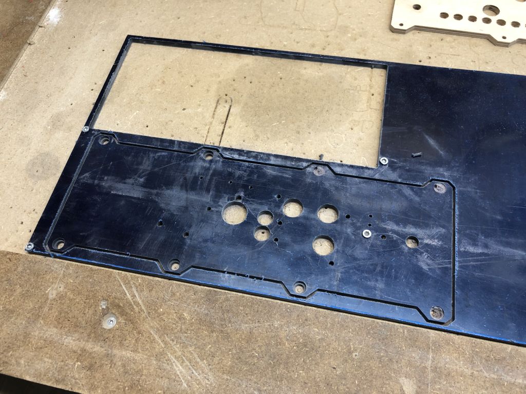
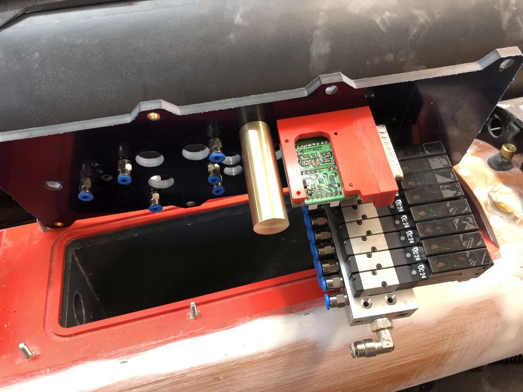
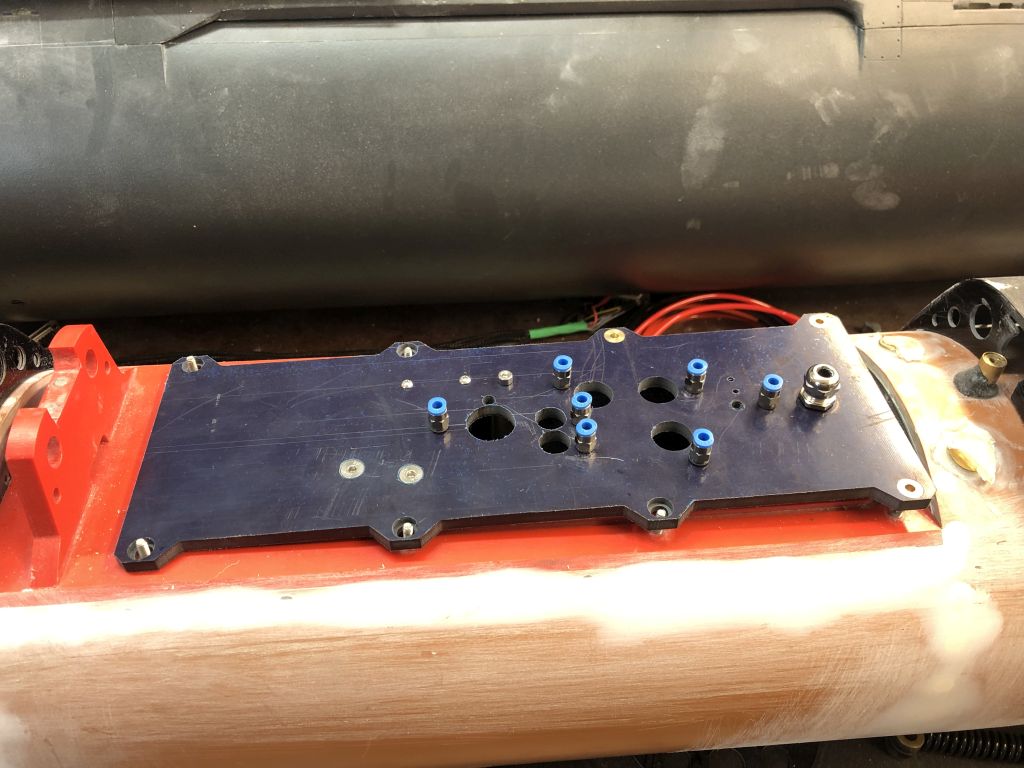
Eines der zeitintensivsten Bauteile stellen die Ausfahrgeräte, oder kurz AFG dar. Der A17 Turm ist nach oben sehr schmal und muss 7 Pressluftzylinder beherbergen. 2 davon sind doppelwirkend, also alles andere als einfach zu bauen. Insgesamt gibt es über 30 Drehteile verschiedenster Größe und Form in und an den Zylindern. Die Zeichnungen dazu habe ich mehrfach angepasst und verbessert, bis alles im CAD passte. Anschließend wurde eine Testplatte aus Sperrholz gefertigt um die Passung zu überprüfen. Schlussendlich konnte dann die eigentliche Platte in 6.5mm GFK gefräst werden. Die einzelnen Masten habe ich in Baugruppen unterteilt und daraus Fertigungszeichnungen erstellt, nach denen die Drehteile hergestellt werden konnten.
Speziell die doppelstufigen FM Masten sind sehr arbeitsintensiv. Insgesamt besteht jeder Mast aus über 20 Drehteilen. Die Dichtheit kann allerdings erst nach dem kompletten verkleben der Anschlüsse getestet werden, aber ich bin guter Dinge das alles funktioniert. Die Überströmkanäle (zum Einfahren der 2. Stufe) der 2. Stufe bestehen aus 2mm Messingrohr, das mit einem kleinen Messingfrästeil jeweils 90° gebohrt und anschließend auf die Manschette verlötet ist. Sehr fummelig und für mich so das kleinste was ich bisher an Druckluftbauteilen hergestellt habe.
Mass Production of Turning Parts and Pistons
One of the most time-consuming components is the extension devices, or AFG for short. The A17 tower is very narrow at the top and needs to accommodate 7 pneumatic cylinders, 2 of which are double-acting, making them far from easy to build. Altogether, there are over 30 turning parts of various sizes and shapes in and on the cylinders. I adjusted and improved the drawings multiple times until everything fit in the CAD. Then, a test plate was made from plywood to check the fit. Finally, the actual plate could be milled from 6.5mm fiberglass (GFK). I divided the individual masts into assemblies and created manufacturing drawings from which the turning parts could be produced.
In particular, the double-stage FM masts are very labor-intensive. Each mast consists of over 20 turning parts in total. However, the tightness can only be tested after all the connections are completely glued, but I am confident that everything will work. The overflow channels (for retracting the 2nd stage) of the 2nd stage are made of 2mm brass tube, which is drilled at 90° with a small brass milling part and then soldered onto the sleeve. It’s very fiddly and the smallest pneumatic component I’ve made so far.